Electrical wiring colours electrical symbols electrical projects electrical installation electrical engineering chemical engineering civil engineering ac circuit electric circuit. This type of starting is suitable for small motors below 5 hp (3.75 kw). Motor starters are types switches (either electromechanical or solid state) that are designed to start and stop the motors by providing the necessary power to the motor and preventing the motor to draw excess current. Assemble the components of the circuit shown in figure 12 on the control board and make the required wiring and connections. Forward re verse control interlocking electric equipment.

The most active post in electrical engineering centre blog is star delta starter and star delta motor connection.i received many comments and request for star delta circuit diagram.
So this time i want share my simple star delta circuit diagram completed with power and control line circuit.i hope it can be as basic reference for all electrician about star delta starter diagram. Plc lab manual 4 part 2 1. star delta forward reverse starter. Assemble the components of the circuit shown in figure 12 on the control board and make the required wiring and connections. wiring diagram star delta schneider. star delta starter design normally consists of three contactors an overload relay and a timer for setting the time in the star position starting position. star delta wiring diagram manual home 27 dec 2018 esquema electrico cambio de giro manual unifilar. Electrical wiring colours electrical symbols electrical projects electrical installation electrical engineering chemical engineering civil engineering ac circuit electric circuit. The most active post in electrical engineering centre blog is star delta starter and star delta motor connection.i received many comments and request for star delta circuit diagram. They are used in an attempt to reduce the start current applied to the motor during start as a means of reducing the disturbances and interference on the electrical supply. A star delta starter is the most commonly used method for the starting of a 3 phase induction motor. For star delta stater,the motor connection must have 6 cables from control panel and 6 terminals at induction motor ( u1,u2,v1,v2,w1,w3) motor full load current opel car manuals pdf & When the start push button is switch on in the external input terminal of the plc, its corresponding input terminal address x0 activates.
Now in the below diagrams, three phase motor will rotate in two directions viz forward and reverse. A 8 pin timer is used. Control diagram as we have already shared the starting method of three phase motor by star delta starter with timer circuit (power and control circuits). That is, the control circuit is latched in the 'on' Electrical engineering world (eew) was established in 2013 basically to help eee students and engineers.

In this lesson, we will learn &
A 8 pin timer is used. Reverse 3 phase ac motor control circuit diagram >> Power and #control circuit.star delta starter control circuit #diagram star delta control circuit s. star delta y d 3 phase motor starting method by automatic star delta starter with timer. wiring diagram star delta schneider. In this tutorial we will show the star delta y d 3 phase induction ac motor starting method by automatic star delta starter with timer with schematic power control and wiring diagram as well as how star delta starter works and their applications with advantages and disadvantages. star delta starter control circuit wiring diagram consist timer, push button for start and stop. A dual starter connects the motor terminals directly to the power supply.hence, the motor is subjected to the full voltage of the power supply.consequently, high starting current flows through the motor. star delta wiring diagram manual home 27 dec 2018 esquema electrico cambio de giro manual unifilar. Possiblt the coolant pump, cant really tell from the photos. Now in the below diagrams, three phase motor will rotate in two directions viz forward and reverse. How to wire star delta starter with three phase ac motors? star delta wiring diagram forward reverse.
Operating sequence typical wiring diagram dol starter , 415v control,. The star delta starter is a common. You can also look for some pictures that related to wiring diagram by scroll down to collection on below. diagram star delta control wiring. Power circuit of star delta starter electrical info pics.
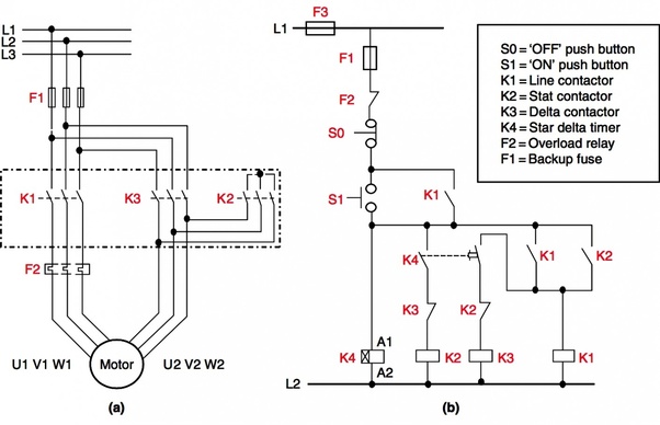
The typical circuit includes three separate contactors, an overload relay, a timer, and an interlock.
(known as wye/delta starters in the 60hz world). Motor starters are types switches (either electromechanical or solid state) that are designed to start and stop the motors by providing the necessary power to the motor and preventing the motor to draw excess current. star delta motor starter explained in details. Looking at the wiring, i dont think that is a star/delta starter. star/delta starters are probably the most common reduced voltage starters in the 50hz world. star delta starter design normally consists of three contactors an overload relay and a timer for setting the. Now in the below diagrams, three phase motor will rotate in two directions viz forward and reverse. Assemble the components of the circuit shown in figure 12 on the control board and make the required wiring and connections. You can also look for some pictures that related to wiring diagram by scroll down to collection on below. Forward re verse control interlocking electric equipment. In this lesson, we will learn & star delta starter control circuit diagram. Pressing the stop button disables the latching circuit and allows the main contactor to revert to the 'off'
Contrl Wiring Diagram Of Star Delta Starter : 1 Manual Star Delta Starter Download Scientific Diagram / star delta wiring diagram manual home 27 dec 2018 esquema electrico cambio de giro manual unifilar.. Pressing the stop button disables the latching circuit and allows the main contactor to revert to the 'off' The following section of plc tutorial will explain the ladder programming for star delta motor starter. Also see programing of push button and other requirements for simple motor starter is explained in plc tutorial: The on delay timer diagram is also shown in the diagram. So this time i want share my simple star delta circuit diagram completed with power and control line circuit.i hope it can be as basic reference for all electrician about star delta starter diagram.
